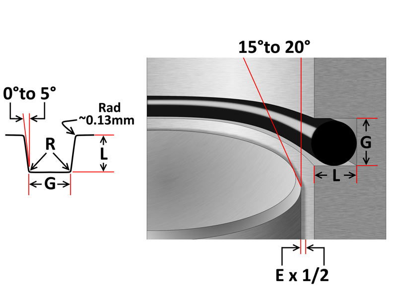
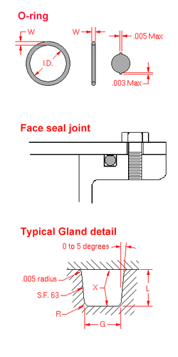
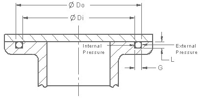
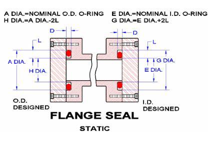
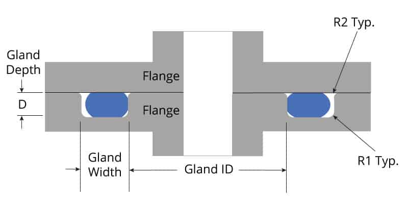
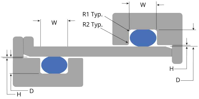
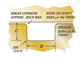
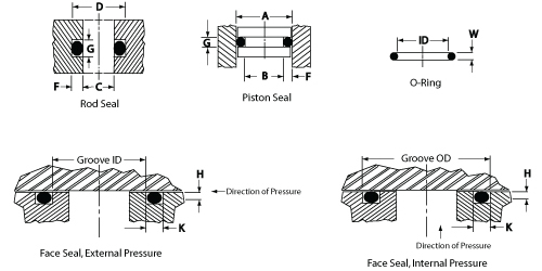
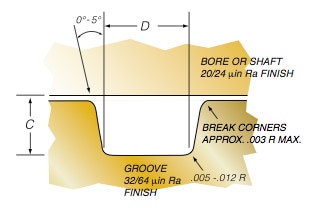
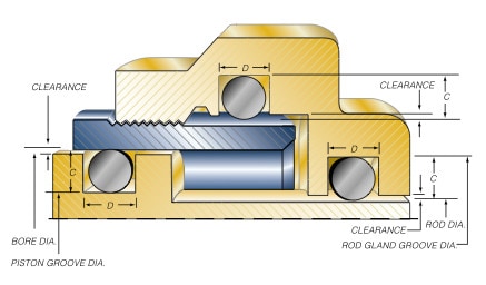
But some sacrifice must be made in the pressure limitations of the seal and also in the life of the sealFor a bore (piston) seal QuadRing® Brand Groove Diameter = Max Bore Diameter – (2 X Recommended Gland Depth) For a face seal QuadRing® Brand Groove Depth = Recommended Gland Depth – Application Clearance With a face seal, if the two surfaces to be sealed are in direct contact (such as with a cover), the seal groove depth is simply theOring seal The tables at the right and the diagram below provide the recommended gland design parameters In addition, the gland surfaces must be free from all machining irregularities, and the gland edges should be smooth and true and free of nicks, scratches, and burrs A perfectly designed Oring seal is of little use if the Oring

Design Of Oring Seals Design Of Oring Seals
O ring seal groove design
O ring seal groove design-Groove Design Technical Data Static ORing Axial (Face Seal) Glands Gland Squeeze Groove Width Groove;If you are designing a face seal, select the ORing with an inside diameter which will position the ORing on the side of the groove opposite the pressure Click here for more information on face seal groove design Note the ORing inside diameter for the next step Calculate the Seal Stretch


O Ring Groove Design Sealing Australia
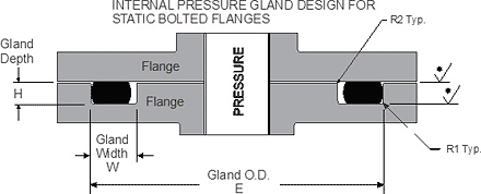
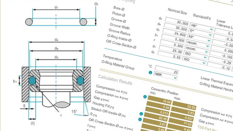
Static oring face seals, used for a wide variety of applications, come in many shapes and forms Whether you need bolted flanges or removable lids, this oring face seal groove design guide will help you choose the right oring for your application ORing Size Charts Oring, xring and square ring size chartsThe ERIKS Oring design calculator features the calculation of • oring dimensions for the use in a specific groove • groove dimensions for the use of a specific oring • evaluation of both, any combination of oring and groove for axial seals with inner or outer pressure, piston seals and rod sealsOring and gland — constitute the classic Oring seal assembly Groove Bore
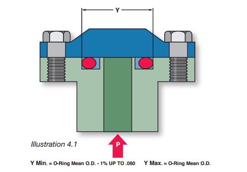
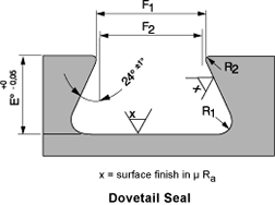
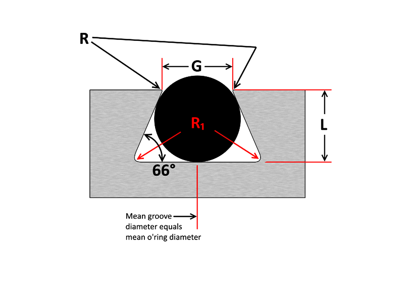
Be it dynamic or static operation, radial or axial loading, vacuum or high pressureGland Design Utilizing Kalrez® ORing Compression Experience with Kalrez® seals has shown that an installed compression (ambient temperature) of 12–18% is suggested for maximum seal life Excessive compression on the Oring seal may result in cracking or splitting of the Oring especially if the Oring is exposed to high temperatures whereAs shown in above figure, an Oring also gets compressed axially in a dovetail groove The groove design allows the Oring to be retained in the axial/face seal during assembly and maintenance This is beneficial for special applications where the Oring has to be fixed by the groove eg a lid which opens regularly
Parker's SealLok ORing Face Seal offers a leakfree seal fitting design and a rugged construction to make it optimal for use in situations with highpressure, vibration and impulse environments WARNING This product can expose you to chemicals including Lead and Lead Compounds which is known to the State of California to cause cancer andIf you are designing a face seal, select the ORing with an inside diameter which will position the ORing on the side of the groove opposite the pressure Click here for more information on face seal groove design Note the ORing inside diameter for the next step Calculate the Seal StretchWARNING Gland Depth x Groove Width (area of the gland) must be larger than the cross section area of the oring (Pi x R^2)Otherwise many bad things will happen to your design Make sure the squeeze % is sufficiently high enough to seal, but low enough to allow dynamic movements


O Ring Groove Design Standard As568b Seal Design Inc


Oring Ehandbook
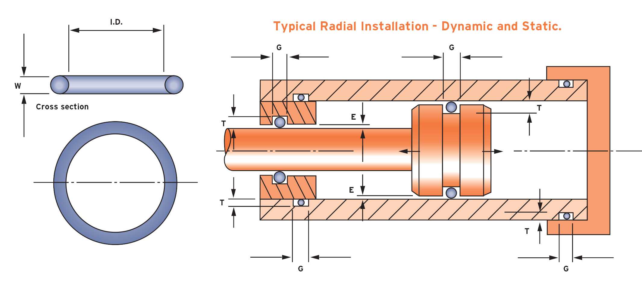
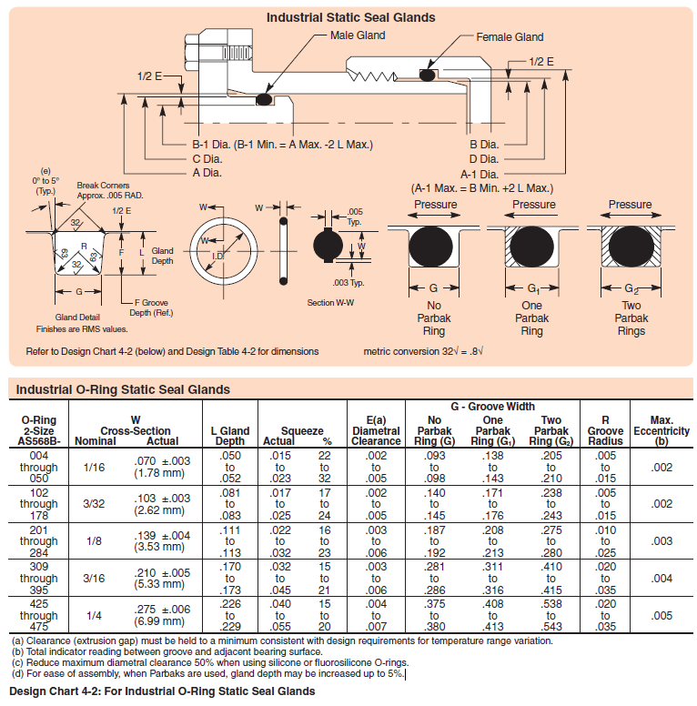
Seal assembly consists of an elastomer Oring and a gland An Oring is a circular crosssection ring molded from rubber (Figure 11) The gland — usually cut into metal or another rigid material — contains and supports the Oring (Figures 12 and 13) The combination of these two elements;Gland Design for Static Application for Orings with Axial Squeeze Surface Finish X groove top and bottom for liquids X = 32 micro inches (08 μm Ra) • Gland Dimensions Static ApplicationFace Seal GlandsMetric W Oring Cross Section E Gland Depth FOring Groove Design in 3 easy steps Step 1 Choose whether you are working with existing hardware or designing new hardware Select the type of Oring groove piston, rod, face seal or trapped seal If the Oring size required is known, simply select the AS, BS or ISO standard (such as AS568) and enter the dash size reference


Ficient Design Static O Ring Groove Design Mechanical Engineering


O Ring Groove Design Guides Engineering Quick Reference
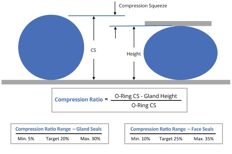
Reciprocating seals may be designed so as to permit or prevent rolling of the ring within the groove When the ring is allowed to roll within the groove, the breakaway force necessary to move the piston is usually lower;QUALITY SEALS GROOVE DIMENSIONS AND MACHINING CONSIDERATIONS 3 Grooves for Static vs Dynamic Seals A Static seal grooves are normally designed to have Between 15%25% squeeze on the ORing Static seals can tolerate higher volume swell of the O Ring than dynamic sealsDesigning Oring seals for low pressures, therefore, is not simply a matter of reducing the amount of squeeze it involves a delicate balancing of material hardness, dimensional tolerances, stress relaxation, and friction characteristics Material Hardness The initial phase of designing a lowpressure Oring seal is the same


O Ring Groove Design Sealing Australia


How To Design An O Ring Groove Vizeng
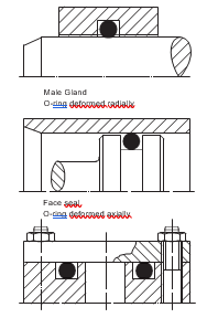
One general guideline for good Oring application and design is to maintain a range of % sqeeze on the Oring (~1040% for static and no more than 30% for dynamic) No less than 75% of the seal crosssection should be contained within the groove to ensure the seal does not "roll" or extrude out of the grooveThe three main types of standard groove designs are Industrial Static also called Radial, Industrial Reciprocating also called Dynamic, and Face Seals also called Axial or Flange Radial and Dynamic seals require the presence of a diametrical clearance gap for installation1 Male or Plug the Oring groove is located on a plug which is inserted into the housing or cylinder (fig 123) 2 Female or Tube the Oring groove is located in the housing or cylinder and a tube is installed through the Oring lD (fig 124) Male or Plug Seal design is based on the following factors (refer to fig 123) Bore Diameter (A)


Parker S O Ring Selector App Youtube


O Rings O Yeah How To Select Design And Install O Ring Seals Tarkka
Dovetail grooves are used to hold the Oring in place during installation or maintenance This groove design is relatively uncommon as it is expensive to machine and should not be used unless absolutely required The dovetail groove construction is only recommended for Orings with cross sections of 139 inch (3,53 mm) and largerRubber Seals, Sealing Devices & ORing Seal Design AppleThe oring gland design is very simple for face seals Simply cut out a circular groove into one of the plates and leave the other plate completely flat, the groove will have a square/trapezoidal cross section and the dimensions are conveniently already calculated and laid out in tables in the Parker Oring Handbook


Metric O Ring Groove Design Reference Guide


What Is An O Ring Selection Material And Storage Barnwell
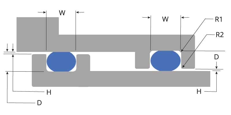
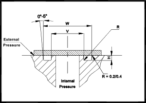
General Engineering Menu ORings Suppliers Molded ORings Services ORings Design Guidelines, Specifications, Materials An Oring , also known as a packing , is a flexible gasket in the shape of a loop;The ORing Store LLC ORing Groove Chart ORing Cord Stock OSK™ Assorted ORing Kits OSK™ ORing Repair Kits OSK™ Hydraulic Seal Kits OSK™ Air Nailer ORing Kits ORing Lube ORing Tools AS568 ORings (Inch) Metric ORings (mm) OSK Pool, Spa & Pump Orings Hydraulic Seals Inch ORing Glue & Thread Sealant Vulcanized ORings ORing Splice Kits & Tools Hydraulic Seals10 ORING SEALS – THEORY AND DESIGN PRACTICES Theory An oring seal consists of an oring and a properly designed gland which applies a predictable deformation to the oring The gland is basically a groove dimensioned to a certain height "H" and width "W" (Figure 1) to allow a fixed compression of the oring


O Ring Groove Design Metric Seal Design Inc


Dovetail Gland Design Dovetail O Ring Groove Dovetail Glands
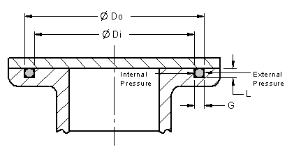
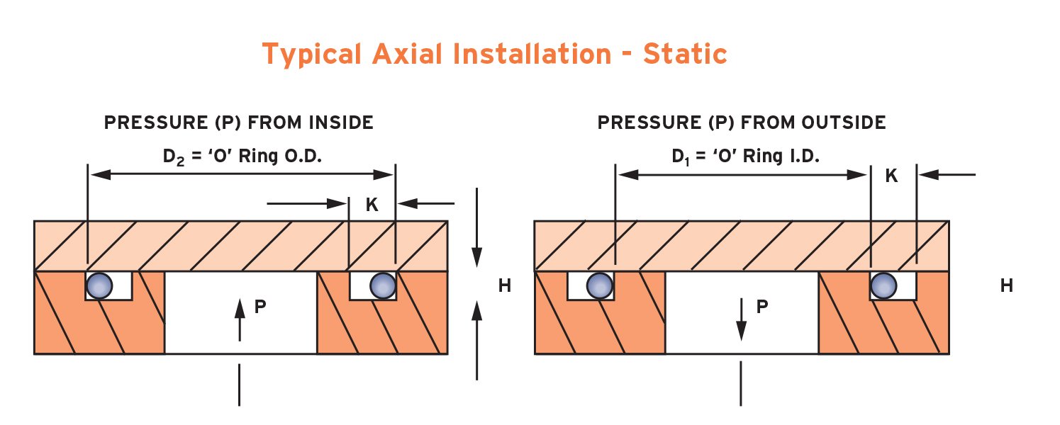
Designing the parts of an application where orings will be applied is broadly termed "oring groove design" In order to seal properly, the oring has to deform in the application by being compressed and stretched in any number of ways The design of the groove where the oring sits plays a major role in how the oring performs its sealingThe face seal design chart below explains the hardware dimensions to use for an Oring seal when the groove is cut into a flat surface For designing systems which contain internal pressure, like the example below, the groove's outside diameter (OD) is primary, and the groove's width then determines the inside diameter The groove is in the 'ceiling' of the application, so I want that the oring is compressed into the groove to prevent it from falling out when the seal is opened The inside circumference needs to be sufficiently small to provide space for the oring to be squeezed
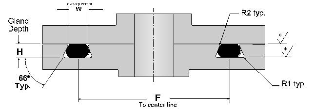


Dovetail O Ring Groove Design Guide A Basic Recommendations


Sealcalc
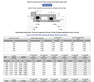
Oring groove design guides offer default dimensional guidance on the most basic oring groove design applications The best orings are useless without the right groove design which becomes increasingly important the more demanding the application environmentThe Oring may be housed in a groove (rod seal) in the cylinder wall instead of a groove in the piston surface (piston seal) without any change in design limitations or seal performance Oscillating A valve spindle is an example of an oscillating applicationOur oring groove design guides list default oring groove dimensions for the most basic applications and are intended to be used with the following oring groove design considerations to engineer on oring gland to optimize specific application performance The wrong size groove makes even the best oring underperform


Buy O Rings Seals Custom Molded Rubber Engineered Plastic All Seals
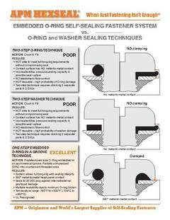


Anyone Have Experience Designing An Asymmetrical O Ring Groove Under A Bolt Head Mechanical Engineering General Discussion Eng Tips
Oring groove design Our customer had a seal that leaked because the groove was oversized We found an existing seal which would solved the problem without the customer having to purchase a new tool Problem Solving Products, Inc 7108 S Alton Way, Unit I Centennial, Colorado (303)Oring groove design is a key consideration in the oring selection process Browse design considerations and recommendations for static face seals, metric orings, static dovetail orings, static rodpiston orings and dynamic rodpiston oringsIf you are designing a face seal, select the QuadRing® Brand with an inside diameter which will position the QuadRing® Brand on the side of the groove opposite the pressure Click here for more information on face seal groove design Note the QuadRing® Brand inside diameter for the next step Calculate the Seal Stretch


What You Need To Know About Designing Axial Seals Hot Topics


Quad Rings All Seals
ORing DimensionsParkerMeanNo 2 ID ± WOD (Ref)000 000 002 000 – † This groove width does not permit the use of Parbak rings For pressures above 1035 Bar (1500 psi), consult Design Chart 42 for groove widths where backup rings must be usedStatic Radial ORing Gland Design In a static radial seal application the oring is squeezed between the inner ID and the outer OD surfaces of the oring, with no relative motion between parts of the gland that come in contact with the oring The table below lists recommended dimensions for static radial seal glands by AS568A oring dashSTANDARD AS568B ORING GROOVE DESIGN The three main types of standard groove designs are Industrial Static, also called Radial, Industrial Reciprocating, also called Dynamic, and Face Seals also called Axial or Flange Radial and Dynamic seals require the presence of a diametrical clearance gap for installation


How To Design An O Ring Groove Vizeng


Design Of Oring Seals Design Of Oring Seals
Total indicator reading between groove and adjacent bearing surface All surfaces and corners must be free of tool marks and scratches ORing groove and dimensions may be calculated as follows (please refer to chart above) Given ExampleAS568B CS Depth Inches % Liquids Gases Radius004 to050 Design Considerations Hardware geometry and limitations are the first consideration A traditional Oring groove shape is rectangular and more wide than deep This allows space for the seal to be compressed, about 25% (for static sealing), and still have some excess room for the seal to expand slightly from thermal expansion or swell from the


O Ring Groove Design Rubber Shop
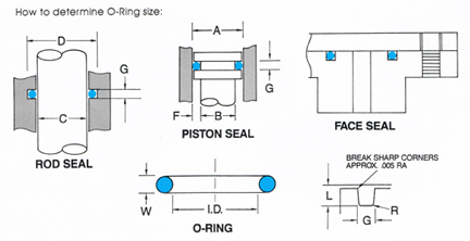


O Ring Groove Design
ERIKS standard ORings and load them also into your created design info chemical volume swell (%) cross section diameter (mm) ISO 3601 free Calculate Results Reset calculatorOring housing data for piston and piston rod sealing applications Type C Type D (0059) (0063) (0070) (0079) 2,40 (0094) 250 (0098) 2,62 (0103) 3,00 3,50 (0138) 3,53 (0139) 4,00 (0157) 5,00 (0197) 5,34 (0,210) (0224) 6,99 (0275) (0331) internal pressure 1For additional information about Oring and backup ring materials, refer to Materials and about extrusion, refer to Gap extrusion Housing groove width To accommodate the additional backup rings, the Oring groove width L needs to be increased to L1 for one backup ring or L2 for two backup rings The groove width dimensions are listed in
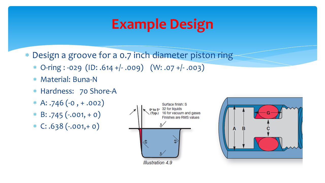


Design Of O Ring Seals Ppt Video Online Download


American Seal Packing General Design And Gland Dimensions
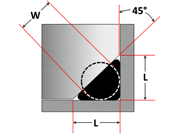
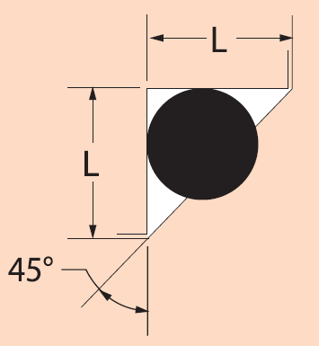
A noncircular face seal footprint might also be called a racetrack groove, a wandering groove or a custom plan view When using an Oring, the main design consideration is the corner or smallest radius (shown "r" in diagram) The inside radius should be at least three times the Oring cross sectional diameterO'ring Groove Design As important as the o'ring seal itself is the groove that the o'ring seats into The groove must be designed to accommodate not just the o'ring size, but also its intended usage;ORing Groove Design 1 The following sizes are not normally recommended for dynamic service, although special applications may permit their use 2 Clearances shown are based on 70 durometer materials The clearances must be held to an absolute minimum consistent with design requirements for temperature variations and should not exceed the


Groove Design Gland Design O Ring Groove Gland Design


O Ring Groove Design Standard As568b Seal Design Inc
Design and dimension the groove that your Oring will go into by researching our Oring Groove Design guide Step 5 Choose a standard size AS568 Oring using this Oring Size Chart Otherwise contact us and we can custom mold any size or shape Oring you needIt is a elastomer with a round crosssection designed to be seated in a groove and compressed during assembly between two or more parts, creating a seal at the interfaceThe primary reason for using a Square Ring in a sealing application is that they perform the sealing function in a superior manner – and at a cost lower than any other comparable sealing device For existing applications, there is no need to change the design or procedures Square Rings fit in oring grooves and are interchangeable sizeforsize


O Rings An Overview Sciencedirect Topics


Sae J1453 O Ring Face Seal Groove Size Chart Knowledge Yuyao Jiayuan Hydraulic Fitting Factory
The Groove Width GW should therefore be about 15 times the ORing crosssection diameter to accomodate this axial expansion, Design Guidelines for Axial Seals ORing design for axial seals is similar to that for radial seals, with the important points summarized below The ORing must be compressed by a predetermined amount, and this


Designing Axial Static O Ring Grooves To Industry Standards Grabcad Tutorials


1


Oring Ehandbook


Groove Design O Ring Seals Minnesota Rubber Plastics


O Ring Installation Design And Specification Static Flange Application Engineers Edge


What Are Static Seals Hot Topics


Static O Ring Face Seal Groove Design Guide


Buy O Rings Seals Custom Molded Rubber Engineered Plastic All Seals


O Ring Groove Design Guides Engineering Quick Reference


O Ring Wikipedia


Oring Ehandbook


How To Design An O Ring Groove Vizeng


Standard Dovetail Grooves Dovetail Groove Engineering Design Guide
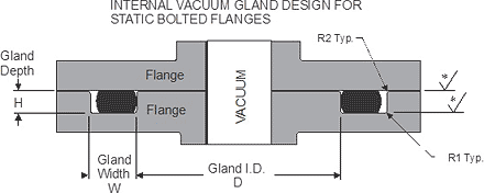


Static O Ring Face Seal Groove Design Guide
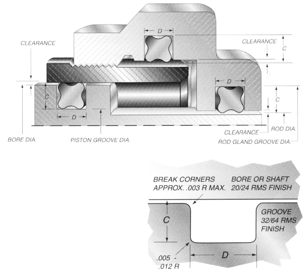


Quad Ring Groove Design Daemar Inc
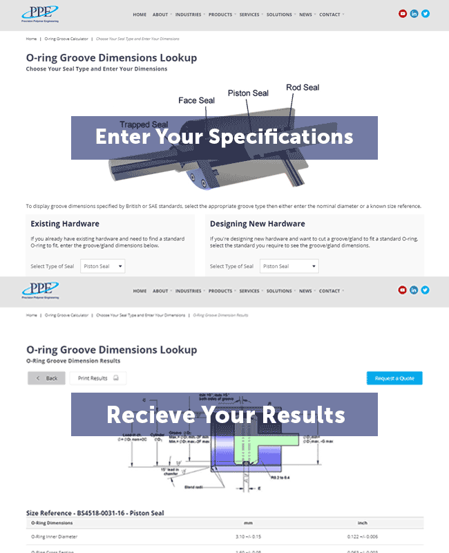


O Ring Groove Dimensions Calculator Precision Polymer Engineering


Seal Design O Ring Design O Ring Design Guide


Buna O Ring O Ring In Houston And Minneapolis Dichtomatik


Static O Ring Gland Design A High Level Run Down By Sean Thomas Linkedin
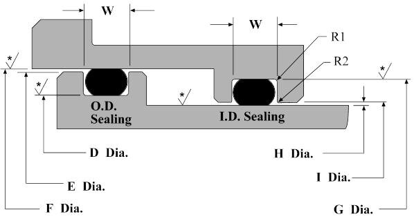


Dynamic O Ring Design Chart Marco Rubber Plastics Custom O Rings Supplier


O Ring Groove Design Global O Ring And Seal


O Rings For Oil Gas Applications Trelleborg


O Ring Info En O Ring Oring Handbook Eriks Sealingelements Technicalhandbook O Rings Oringapplications Pdf


How To Use An O Ring In A Non Circular Groove Pattern


1


O Ring Groove Depth T O Ring Groove Width B Radial An Axial O Ring Fitting


4 Common Mistakes In Designing For An O Ring Axial Face Seal Hot Topics


New Gland Calculator Tool At Applerubber Com Official Apple Rubber Blog


O Ring Groove Design Seal Design Inc


O Ring Groove Design Sealing Australia


Gland Design Oringsusa


O Ring Groove Design Seal Design Inc


Seals Eastern Flange Seal O Ring Design Guideline


O Ring Groove Design Global O Ring And Seal


How To Use An O Ring In A Non Circular Groove Pattern


O Ring Cross Section O Ring Groove Design Data


O Ring Groove Design Global O Ring And Seal
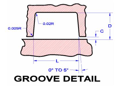


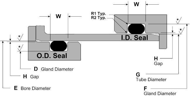
Seals Eastern Plug Seal O Ring Design Guideline
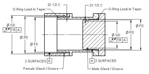


O Ring Installation Design And Specification Static Cylindrical Installations Engineers Edge


O Ring Groove Drafting Standards Gd T Tolerance Analysis Eng Tips


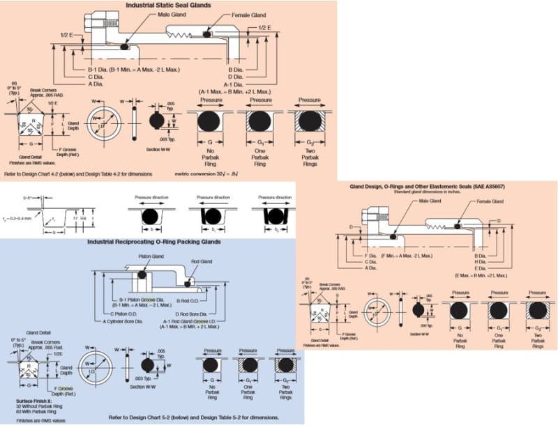
Static O Ring Design Chart Marco Rubber Plastics Custom O Rings Supplier


Efunda Introduction To O Rings
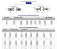


O Ring Groove Design Guides Engineering Quick Reference
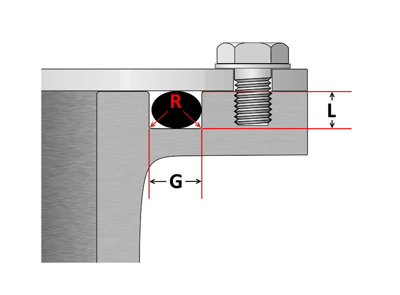


O Ring Groove Design Sealing Australia


Dynamic Rotary Gland Design Dynamic O Ring Gland
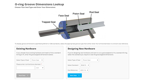


O Ring Groove Dimensions Calculator Precision Polymer Engineering
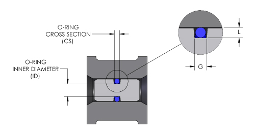


O Ring Groove Design O Ring Groove Dimensions Mykin Inc


Www Hitechseals Com Includes Pdf O Ring Brochure Pdf


Groove Design Quad Ring Seals Minnesota Rubber Plastics


2 Design And Detail Information O Rings Stock O Ring Webshop


Www Hitechseals Com Includes Pdf O Ring Brochure Pdf


O Ring Groove Design Global O Ring And Seal


Fep O Rings Trelleborg Sealing Solutions


O Ring Seals Roy Mech


Design Of Oring Seals Design Of Oring Seals


O Ring Groove Design Daemar Inc


O Rings O Yeah How To Select Design And Install O Ring Seals Tarkka


O Rings O Yeah How To Select Design And Install O Ring Seals Youtube


What Is An O Ring Selection Material And Storage Barnwell


O Ring Groove Design Seal Design Inc


Groove Design Gland Design O Ring Groove Gland Design


Groove Design O Ring Seals Minnesota Rubber Plastics


Seals Eastern O Ring Rod Seal Design Guideline


O Ring Groove Design Guides Engineering Quick Reference


O Ring Groove Design Sealing Australia


O Rings Designing


1


1


Oring Ehandbook


Triangular O Ring Grooves Mechanical Seal Engineering Eng Tips


O Ring Groove Design Seal Design Inc


Dynamic Reciprocating Gland Design Dynamic O Ring Gland


Groove Design O Ring Seals Minnesota Rubber Plastics


O Ring Groove Design Global O Ring And Seal


Ruander Com Quick O Ring Groove Design Guide
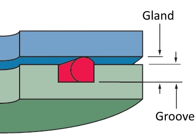


4 Common Mistakes In Designing For An O Ring Axial Face Seal Hot Topics


0 件のコメント:
コメントを投稿